RECENT ARTICLES

John Walt Childers
IPC-CID
Thu 15/Nov 18

Golden Gate Graphics is an Altium Designer certified printed circuit board design service bureau
Altium Designer 18 User Interface Can Be Light Gray
It can be made to resemble Altium Designer 17 and earlier versions. The light gray interface is useful for making screen shots destined for print media. See below.
Altium Designer 18 Ships with a Dark Gray Interface.
It looks like the screen shot below. If you’re using a desk top computer, right-click the image and select “Open Image in New Tab” to get a better view of it.
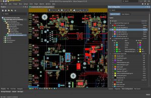
Altium Designer 18 User—Interface Dark Gray
I make screen shots for print media. Unfortunately, that user interface will result in a lot of ink on the page. Therefore, I set the user interface to Light Gray.
Light Gray User Interface for Altium Designer 18
Here is an example of the light gray interface.
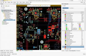
Altium Designer 18 User—Interface Light Gray
How to set up the light gray user interface.
Open the Preferences dialog

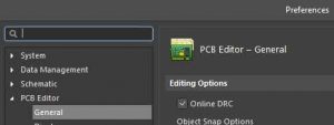
Choose System, View

Change User Interface Theme to Altium Light Gray.
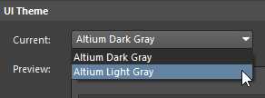
You’ll get a warning—you have to re-start Altium for the new UI Theme change to take effect.

Screen shots with white board area will also conserve ink in print media.
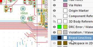
To take things further, you can change the board area to white as shown below.
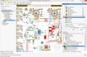
Altium Designer 18 UI Light Gray with White Board Area
Change board area to white by using the View Configuration. Hot key (keyboard shortcut) is Ctrl-D. Then select the Layers & Colors tab.
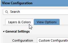
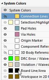
Change the Board Area color to white.
LED Boards
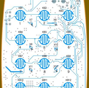
This is a side note on LED Boards. These use white solder mask and black legend (overlay or silk screen). Hence, if you are designing an LED board, you can make the work space view in Altium resemble it by setting the board area color to white and the legend to black.
White solder mask reflects light very well. I am typing this text on a Code ™ mechanical LED back-lit keyboard. It uses white solder mask on the main board.
Below is a screen shot of a back-lit keypad that I designed.
3D View Configurations Can Be Very Life-Like
You can also set the solder mask and legend colors in the 3D view of the board. Look carefully in the image below and you can see the mouse cursor arrow pointing to the white color box for the Bottom Solder Mask.
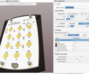
3D View Configuration with White Solder Mask
Here’s a plug for great screen capture software—Capture Wiz can capture momentary graphics like a cursor position. Capture Wiz was used for all these screen shots. Its use is invaluable to describing and teaching Streamlined PCB Design.
© 2018 John Walt Childers Latest revision 11/15/2018 10:23 PM
Design For Assembly-HDI Prevention of Solder Bridging
Design For Assembly - Prevention of Solder Bridging in High Density Interconnect PCB Components This is an advanced DFA technique developed by Cherie Litson in working with Microsoft engineers on the PCB design and manufacturing [...]

